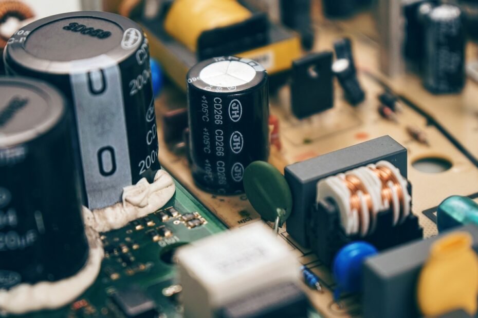
The pre-charge circuit is a critical aspect of any high-voltage system with a capacitive load. Pre-charging prevents high inrush currents from damaging system components when the high-voltage source first connects to the capacitive load.
Background
Connecting a voltage to a capacitance causes an instantaneous current spike. Current can change instantaneously over a capacitor while voltage cannot. When the source voltage is first connected, current rushes in to fill the capacitance. The capacitor voltage then gradually increases until it equals the source voltage.
The current inrush happens right as the voltage source is connected to the capacitive load. During the transient period that follows, the current starts at its maximum value and decreases exponentially. At the same time, the voltage across the capacitor starts at zero and increases asymptotically. This continues until the capacitor is “fully” charged, i.e. the capacitor voltage is very close to the source voltage.
Pre-charging is used in electric vehicles, where the Lithium Ion battery voltage is anywhere from 400-1000 VDC and the motor inverters have input capacitors. It might also be necessary in hobby electric vehicles, such as electric bikes, go-karts, RC airplanes, boats, or battle robots. It all depends on the system voltage, capacitance, and circuit resistance. Inrush currents can be damaging in any circuit with high voltage, low resistance, some capacitance, and where the load is connected and disconnected from the source with a switch.
Pre-Charge Circuit Design
Pre-charging uses a small current to “fill” the system capacitance with charge before the main contactors are switched closed. A pre-charge circuit consists of a contactor and resistor in series. This circuit connects in parallel to the main contactor that switches the battery into the load.
A pre-charge circuit is modeled as an RC circuit. Standard formulas are used to determine the resistor value required to pre-charge the capacitance to a given percentage of battery voltage within a desired time.
The design workflow is typically to start with a desired pre-charge time and charge percentage. 5 time constants (5𝛕 = 99.326%) are recommended to fully charge the capacitance. The pre-charge time is minimized to not to keep the driver waiting too long. The charge percentage is how “full” the capacitance needs to be at the end of pre-charging. The more full the capacitance, the smaller the inrush current will be after pre-charging. These inputs are used to calculate the maximum resistance that will allow this desired pre-charging scenario.
Pre-charging faster is better for user experience, but of course there are tradeoffs. Faster pre-charging means the pre-charge resistor has to absorb more energy in a shorter period of time. This drives a larger resistor with a higher power rating to minimize heat, which increases cost.
Pre-Charge Whitepaper and Calculator
A colleague and I recently wrote this whitepaper that goes deeper into pre-charge circuits in electric vehicle applications. Be sure to check it out!
We also made a live calculator to analyze a pre-charge circuit design. Check that out here.
Enjoy! §
