Ultrasonic sensing can be great for measuring short distances. Pair an ultrasonic sensor with an Arduino and a simple display and you have a handheld object detector.
How Ultrasonic Sensing Works
Ultrasonic sensors emit high-frequency sound waves (hence the name “ultra” sonic) and measure the time it takes for them to return. The farther away an object is, the longer it will take the sound to bounce off it and travel back.
Handheld Application
A wearable device startup asked me to prototype a handheld object detection device to aid blind and visually impaired people. The goal was to eventually incorporate the object detector into a wearable device.
A handheld application requires the device to work under all circumstances that people find themselves in regularly. For example, it should measure accurately in both light and dark conditions, which ultrasonic sensing does because it uses sound instead of light.
It should also be robust to noise interference and it should not generate audible noise itself. Noise interference could theoretically alter the measurements, although ultrasonic sensors operate in frequency ranges far above audible noise, so this is usually not a problem. This also means an ultrasonic sensor will not generate noise that anyone can hear.
The object detector should be robust to changes in orientation. Moderate impacts should also not impair function, as the user would likely knock the device around a bit in their hand.
Object Detector Design
My approach was to build a simple object detector to test how well it perceived obstacles. In theory, an ultrasonic sensor should work for this, but the only way to know whether such a design would have an intuitive feel for humans would be to test it.
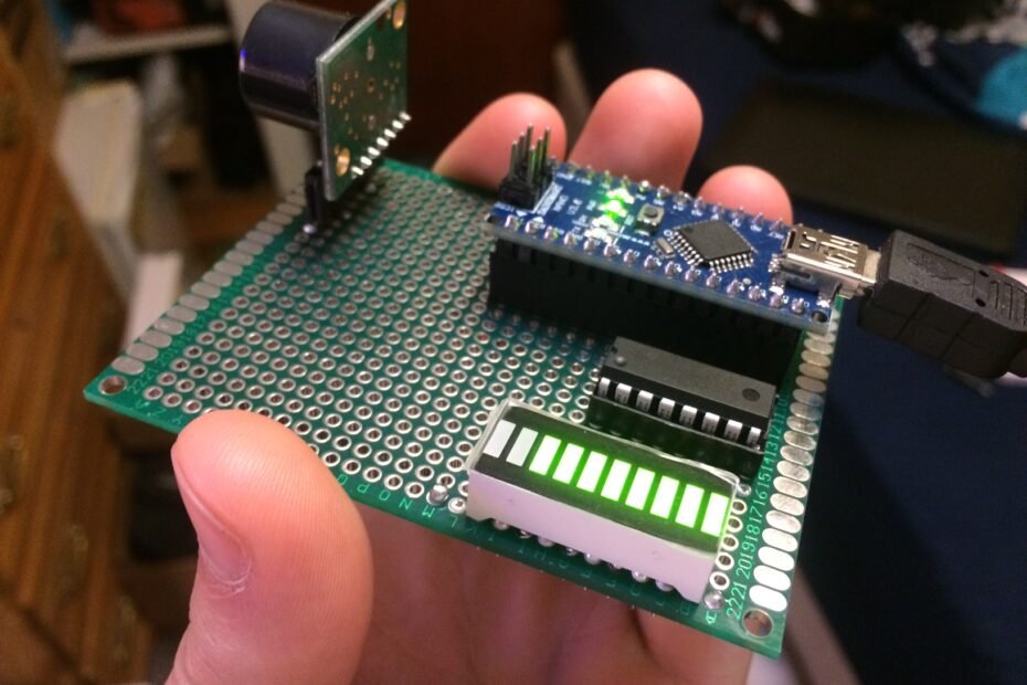
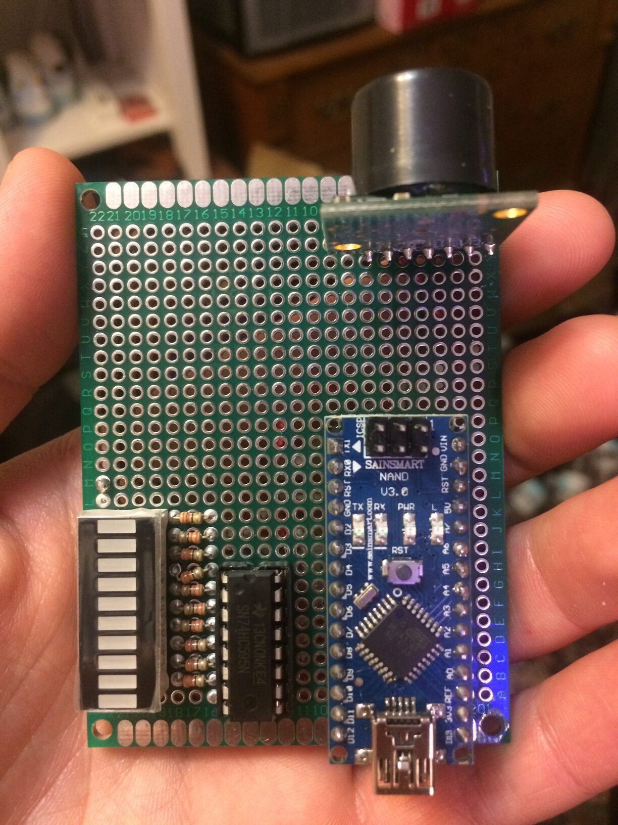
I designed and built a simple device consisting of four main components – an ultrasonic sensor, an Arduino Nano, a 10-LED bar graph display, and an 8-bit shift register to control the LEDs. I read the sensor input into the Arduino and mapped it to the 10-position LED bar graph component. This component is simply a block of 10 independent LEDs, each of which I controlled with separate digital outputs between the shift register and Arduino.
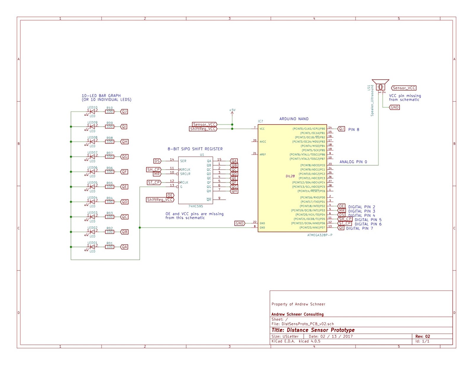
Below is the circuit schematic which I made with KiCAD.
Software
I started by directly mapping the sensor signal to the LED bar graph. The first problem I had was that the mapping was backwards, so close objects caused the lights to turn off rather than turn on. The video below shows the first test.
This problem was easily fixed in software.
However, the most unexpected challenge was how unusable the raw sensor signal was. The signal was too noisy, causing the LEDs to fluctuate very quickly. This made the display annoying to look at. I corrected this with a moving average filter to slow down the rate of change of the signal.
The sensor range was also poorly calibrated to the types of objects and distances I wanted to detect. For example, it was too “all or nothing.” It either didn’t detect anything at all, or oversaturated very quickly when an object came within view. To mitigate this, I used signal processing to effectively flatten out the sensor’s transfer function to make it less sensitive and more linear, and thus respond more gradually to changes in object distance.
This video shows a more polished prototype with some improvements:
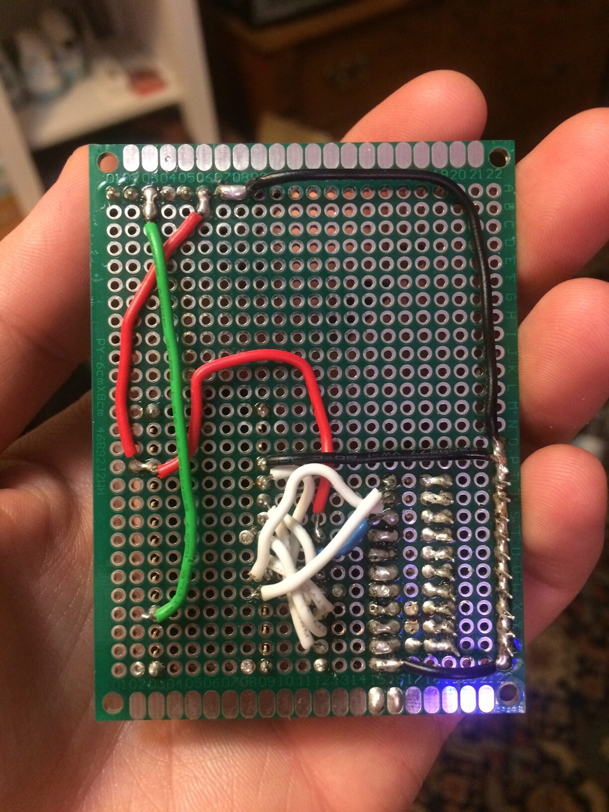
The final video below shows the finished prototype. The behavior of the LED bar graph was much more intuitive after the software corrections were made. This video shows the workmanship and board layout in more detail as well.
Thanks for reading! §